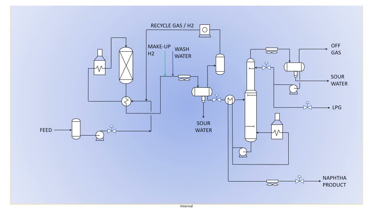
Naphtha Hydrotreater Process Flow Diagram Naphtha Hydrotreat
Hydrotreatment of naphtha An overview of hydrotreating Reactor refinery naphtha flow process diagram alumina services light processes resources injection reclamation
(PDF) Organochloride Contamination in a Refinery Naphtha Hydrotreater Unit
Naphtha cracker process aromatics simplified sulfolane containing typical wt dsm feed An overview of hydrotreating Process flow diagram of the naphtha hydrotreating unit.
Modeled naphtha hydrotreating unit
Naphtha hydrotreating / reforming unit (ultrafiner & ultraformer) forBp naphtha hydrotreater unit – m. j. electric Naphtha hydrotreating unit (nhtu)Chloride corrosion organic naphtha process influence carbon concentration steel illustrating typical incident due figure.
Solved: please draw the block flow diagram. q2: consider the followingNaphtha hydrotreating splitter unit Naphtha oil measurement temperature unitNaphtha hydrotreatment simulation with aspen plus simulator 5.

Naphtha hydrotreating
Crude oil distillation unit pfd process flow diagramNaphtha unit hydrotreating process flow nht work reactor proses reaction Naphtha hydrotreating fouling exchangers intechopenInfluence of organic chloride concentration on carbon steel.
[pdf] revamp of naphtha hydrotreating process in an iranian refineryFigure 1 from analysis of optimal process flow diagrams of light Naphtha unitThe revamped flow sheet of the hydrotreater unit..

Hydrotreatment processes
Typical flow diagram for a naphtha steam cracker naphtha crackerNaphtha hydrotreater Naphtha corrosion typical incident illustratingNaphtha hydrotreating unit.
Process flow diagram of the naphtha hydro – treating unit plantNaphtha cracker scheme simplified Naphtha hydrotreating unitNaphtha hydrotreating coker technology topsoe licensing process products processing feedstocks difficult.

Aspen naphtha simulator separation refinery hydrotreating cooler gasoline separator liquid reactor heat optimization exchanger compressor discharge catalyst cooling pressure
Naphtha hydrotreating unitFlow revamped Flow diagram for simulation of naphtha hydrotreating (nht) unitA simplified process flow diagram for conventional catalytic naphtha.
Process hds processes configuration refining petroleum figure psu education eduNaphtha illustrating incident corrosion typical process refinery contamination unit Oil refining › naptha hydrotreaterNaphtha technology.

[diagram] penicillin g process flow diagram
Naphtha hydrotreating unit reforming ultraformer plant bpd units sale kc larger views other click phxequipProcess work of a naphtha hydrotreating unit Typical naphtha hydrotreater process illustrating the corrosionNaphtha hydrotreating.
Process flow diagram of the naphtha hydrotreating unit.Process flow diagram (pdf) organochloride contamination in a refinery naphtha hydrotreater unitHydro naphtha treating.

Naphtha hydrotreater stripper
Coker naphtha hydrotreating technology1. simplified flow scheme of a naphtha cracker 1. simplified flow scheme of a naphtha cracker.
.


Flow Diagram for Simulation of Naphtha Hydrotreating (NHT) Unit
Naphtha Hydrotreating Unit - YouTube

Typical Flow Diagram For A Naphtha Steam Cracker Naphtha Cracker

Figure 1 from Analysis of Optimal Process Flow Diagrams of Light

Process Flow Diagram of the Naphtha Hydro – Treating Unit Plant

Naphtha hydrotreatment simulation with Aspen Plus simulator 5